Printing Weather Sensor Measurements in I2C LCD on ESP32 using Arduino IDE
Hello, again!
So last time, I wrote about trying the I2C LCD on an ESP32 Development Kit using the Arduino IDE to print text outputs on it. Also, I have posted an article showing you how to use the DHT11 weather sensor features. Today I plan to show you how to combine those two projects into one, simply by printing out the weather measurements on the I2C LCD. The weather measurements for this project will be measured using two different sensors, first the DHT11 then the BME280.
Segment 1 - DHT11
Step 1: Hardware Requirement
Everything you will need is:
- 1 Laptop/PC
- 1 ESP32 Development Board
- 1 MicroUSB cable
- 1 DHT11 Weather sensor
- 1 Resistor (330kOhm)
- Male-Female Jumper Wires
- Male-Male Jumper Wires
- Female-Female Jumper Wires
Basically, every software requirement needed is just the same as in the "Blinking program" I wrote before. If you haven't checked it out, you can click here and look for Step 2: Software Requirement. For each sensor you plan to use, make sure to install the needed libraries that come for it through the Library Manager in the Arduino IDE.
Step 3: Circuit
Remake the following circuit using the equipment you have prepared before.

Note: Make sure to use the same pin numbers as the ones you will be defining in your Arduine code.

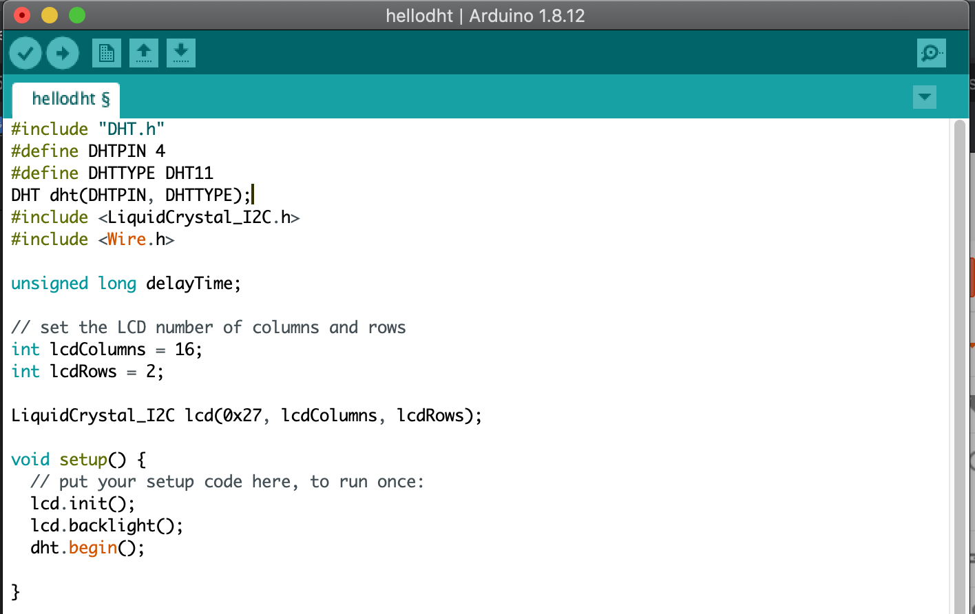
Step 4: Code
Use this code below in the Arduino IDE. If you have read the DHT11 and LCD article I have written you might notice that this is just a simple union consisting of the two codes from the previous codes I used before.


Step 5: Compile, Upload & Observe
After you have succeeded uploading the code and constructed the circuit you will see how the LCD is running the loop in the code.

Segment 2 - BME280
Step 1: Hardware Requirement
Everything you will need is:
- 1 Laptop/PC
- 1 ESP32 Development Board
- 1 MicroUSB cable
- 1 Resistor (330kOhm)
- 1 BME280 weather sensor
- Male-Female Jumper Wires
- Male-Male Jumper Wires
- Female-Female Jumper Wires
Step 2: Software Requirement
Basically, every software requirement needed is just the same as in the "Blinking program" I wrote before. If you haven't checked it out, you can click here and look for Step 2: Software Requirement. For each sensor you plan to use, make sure to install the needed libraries that come for it through the Library Manager in the Arduino IDE.
Remake the following circuit using the equipment you have prepared before.


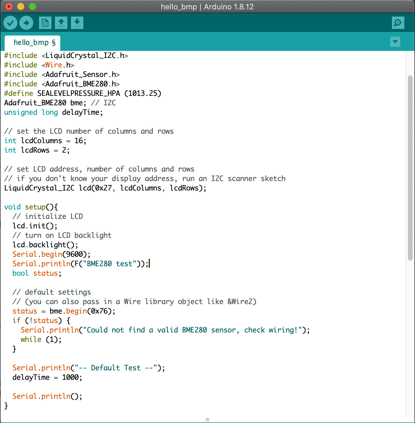
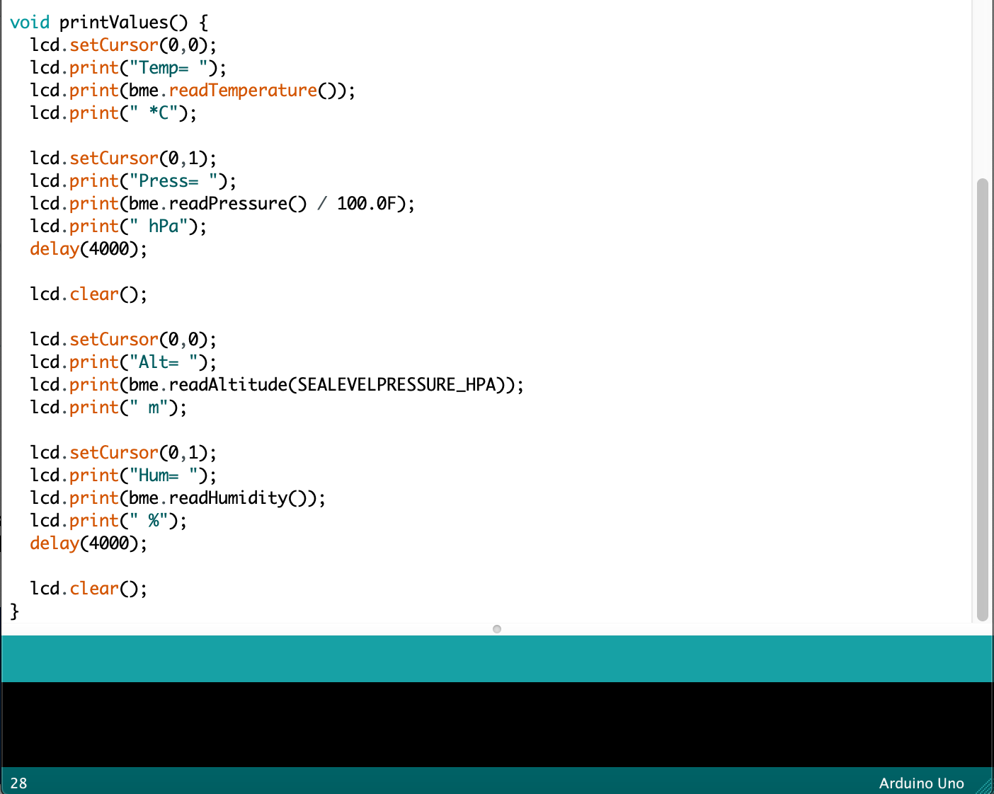
Step 4: Code
Use this code below in the Arduino IDE.


Step 5: Compile, Upload & Observe
After you have succeeded uploading the code and constructed the circuit you will see how the LCD is running the loop in the code.
Voilà! See you next time!


Comments
Post a Comment